The Inverter protection circuit – LM324 the low voltage and overload issue controlling. free PCB layout ( suitable for using ic SG3525, Sg3524, etc. ).
it is a very important and useful circuit board for inverter voltage detection and shutdown to protect electrical equipment.
if the battery voltage is low the buzzer starts to beep.
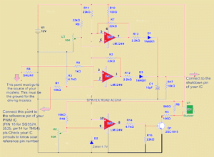
Inverter protection circuit diagram
Components required
- LM324 ic —————————————————1
- 22k resistor———————————————–3
- 10k preset pot———————————————2
- 2.2k resistor———————————————–2
- 4.7v zener diode——————————————1
- 10k resistor—————————————–4
- 4.7k resistor—————————————–2
- 100ohm resistor——————————2
- 560-ohm resistor—————————————1
- 1k ohm resistor ————————————-1
- 10uf 25v capacitor———1
- 547 transistor ——-1
- 1n4007 diode ——1
- piezo buzzer—–1
if the overload has to be detected on the output the circuit will turn off the ic.
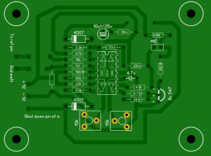
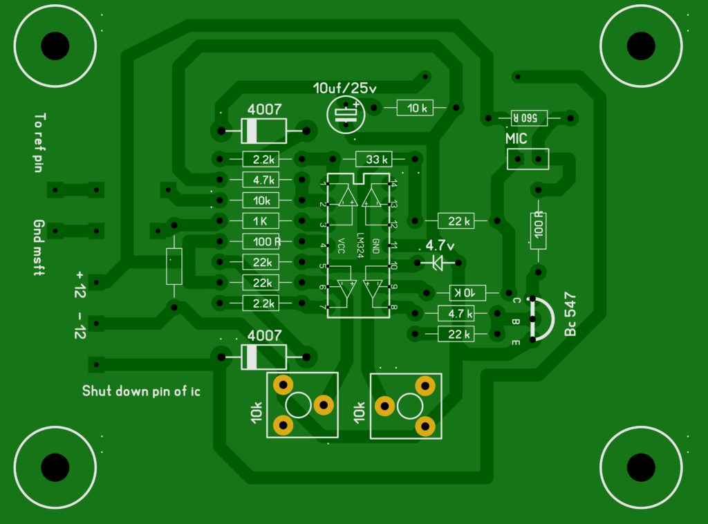
in this board, the two preset pot will allow you to adjust the low voltage and overload setting.
adjust the pot to your convenience.
if the voltage is below the required voltage then the circuit will be turned on and starts to beep.
if the battery volt is very low voltage the circuit will shut down the PWM ic.
There are three output connections are available, one is the point must go to the source of your MOSFETs, this must be the ground for the driving MOSFET
The second pin comes from the ic pin 2 this connected to the reference pin of your PWM ic. in sg3524 and sg3525, the reference pin is 16.
and the third output pin that connects to the shutdown pin of your PWM ic.


There seem to be a resistor between negative of battery and mosfet source. What value is it please?
OK, which inverter circuit? Can I have the inverter circuit it works with sir??
Good morning, after constructed the circuit, it doesn’t works when connected to inverter
its working my friend