Introduction
An electrical transformer is a device that is used to transfer electrical energy from one circuit to another through electromagnetic induction.
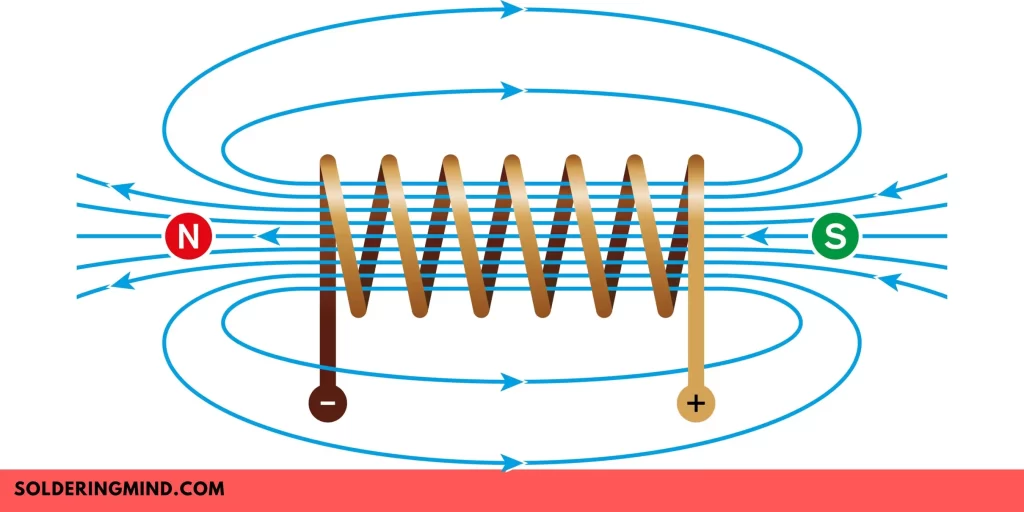
It works on the principle of Faraday’s law of electromagnetic induction, which states that a changing magnetic field can induce an electromotive force (EMF) in a nearby conductor.
Transformers are widely used in the electrical power system to step up or step down the voltage of an AC power supply, as it is much more efficient to transmit electrical power at high voltage and low current.
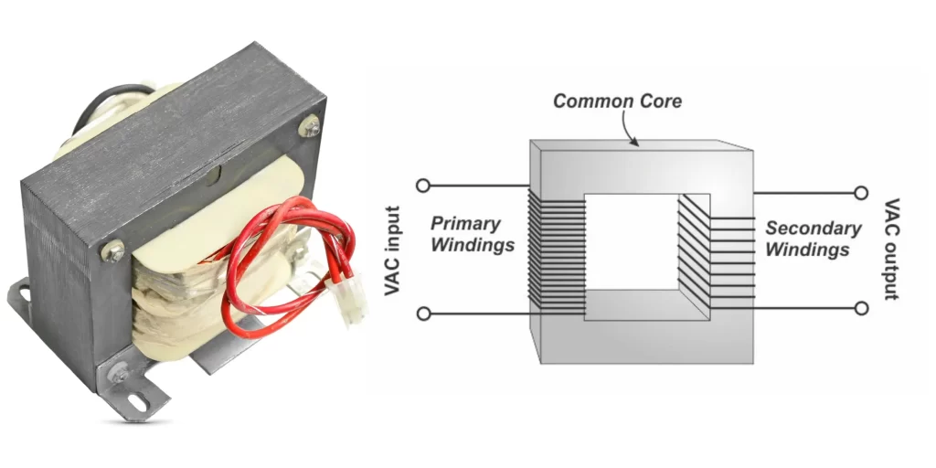
The transformer consists of two or more coils of insulated wire wound around a magnetic core. The coil connected to the input voltage is called the primary coil, and the coil connected to the output voltage is called the secondary coil.
When an AC voltage is applied to the primary coil, it generates a magnetic field that induces an AC voltage in the secondary coil, which is proportional to the number of turns in the secondary coil. By changing the number of turns in the primary and secondary coils, the transformer can be used to step up or step down the voltage of the AC power supply.
Transformers are used in a wide variety of applications, such as power transmission, distribution, and consumption, and they are an essential component of the modern electrical power system.
Also Check : Ferrite Core transformer Specifications
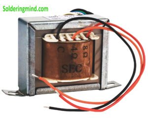
Electrical Transformer Winding
Transformer windings are coils of wire that are wound around a magnetic core to create an electromagnetic field. The windings are a crucial component of a transformer and are responsible for transferring electrical energy from one circuit to another through electromagnetic induction.
In a transformer, there are usually two windings: the primary winding and the secondary winding. The primary winding is connected to the input voltage, while the secondary winding is connected to the output voltage.
When an AC voltage is applied to the primary winding, it generates an alternating magnetic field that induces an AC voltage in the secondary winding, proportional to the turns ratio of the transformer.
The number of turns in the windings determines the voltage transformation ratio of the transformer. A higher number of turns in the secondary winding compared to the primary winding will result in a step-up transformer, while a lower number of turns in the secondary winding compared to the primary winding will result in a step-down transformer.
The windings can be made of various materials, such as copper or aluminum, and can be insulated to prevent electrical shorts between the turns.
In addition to the primary and secondary windings, a transformer may also have additional windings, such as tertiary or quaternary windings, for specific applications.
Transformer windings can be wound in different ways, such as concentric, helical, or layer winding. The winding technique can affect the transformer’s electrical characteristics, such as the distribution of the magnetic flux and the leakage inductance.
The winding configuration can also be modified to create specialized transformers, such as autotransformers, multi-winding transformers, and resonant transformers.
Iron core Transformer Winding Formula
The iron core transformer winding formula is given by:
N = (V x 10^8) / (4.44 x f x B x A)
where: N = number of turns in the winding V = voltage of the power source f = frequency of the power source in Hertz (Hz) B = maximum flux density in the core in Tesla (T) A = cross-sectional area of the core in square meters (m^2)
This formula is used to calculate the number of turns needed in the transformer winding to achieve the desired voltage transformation ratio, given the characteristics of the core and the power source.
The formula is based on the principle that the voltage induced in a transformer winding is proportional to the number of turns in the winding, the frequency of the power source, and the magnetic flux density in the core.
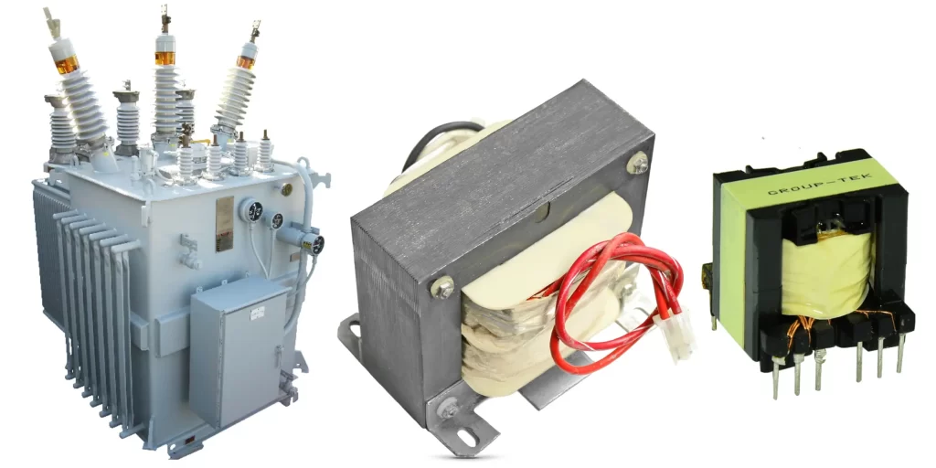
Types of Electrical Transformers
| Transformer Type | Basic Characteristics |
|---|---|
| Step-up transformer | Increases the voltage of the input voltage. |
| Step-down transformer | Decreases the voltage of the input voltage. |
| Isolation transformer | Provides electrical isolation between the input and output voltage. |
| Autotransformer | Uses a single winding as both the primary and secondary winding. |
| Current transformer | Measures the current flowing in a circuit and provides a proportional current output. |
| Voltage transformer | Measures the voltage in a circuit and provides a proportional voltage output. |
| Distribution transformer | Used to step down the high voltage electricity from power stations to lower voltage levels for distribution. |
| Power transformer | Used to transmit and distribute large amounts of electrical power over long distances. |
| Audio transformer | Used in audio equipment to couple different stages of amplification or match impedances. |
| Instrument transformer | Used to measure or monitor electrical parameters, such as current or voltage, in high voltage systems. |
Electrical Transformer Construction
An electrical transformer typically consists of the following components:
- Core: The core is the magnetic structure around which the transformer windings are wound. It is usually made of a ferromagnetic material such as laminated silicon steel, which reduces energy losses by minimizing eddy currents.
- Windings: The windings are coils of wire that are wound around the core. The primary winding is connected to the input voltage, and the secondary winding is connected to the output voltage. The number of turns in the windings determines the voltage transformation ratio of the transformer.
- Insulation: The windings are typically insulated to prevent electrical shorts between the turns. This insulation can be made of materials such as paper, cotton, or polymer films.
- Tap changer: is a mechanism that allows for the adjustment of the transformer’s output voltage by changing the number of turns in the winding. This is achieved by tapping off the winding at different points.
- Tank: The tank is the outer shell that encloses the core and windings. It is typically made of steel and serves to protect the transformer from environmental factors such as moisture and dust.
- Cooling system: Transformers generate heat during operation, and it is essential to dissipate this heat to prevent damage to the transformer. The cooling system can be either air-cooled or liquid-cooled, and it typically consists of radiators or heat exchangers.
- Bushings: Bushings are insulated devices that provide a means of connecting the transformer windings to the external electrical system.
The construction of a transformer can vary depending on its size, application, and operating conditions. Larger transformers, such as those used in power transmission, may include additional features.
such as on-load tap changers, protective devices, and monitoring systems to ensure safe and reliable operation.
Design of an Electrical Transformer
The design of an electrical transformer involves several considerations, such as the required voltage transformation ratio, the frequency of the input voltage, and the power rating of the transformer. The following are the design parameters of a transformer:
Core design:
The core design involves selecting the shape and size of the core to minimize energy losses and optimize the magnetic flux distribution. The core material should have a high permeability to ensure efficient energy transfer.
Winding design:
The winding design involves selecting the number of turns in the primary and secondary windings, the cross-sectional area of the wire, and the insulation material. The winding design determines the voltage transformation ratio and the current carrying capacity of the transformer.
Cooling system design:
The cooling system design involves selecting the appropriate cooling method, such as air or liquid cooling, and designing the heat exchanger or radiator to ensure efficient heat dissipation.
Efficiency and losses:
Transformer efficiency is a critical design parameter and can be affected by various factors. They are core losses due to hysteresis and eddy currents, winding losses due to resistance, and stray losses due to leakage flux. The design should aim to minimize these losses to maximize efficiency.
Voltage regulation:
Voltage regulation is the ability of the transformer to maintain a constant output voltage despite variations in the input voltage and load. The design should ensure that the voltage regulation is within acceptable limits.
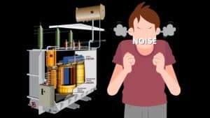
Noise and vibration:
The design should consider reducing noise and vibration to ensure a quieter and more stable operation of the transformer.
Transformer design is a complex process that requires consideration of many interrelated factors. Computer-aided design (CAD) software is often used to simulate and optimize the design before fabrication.
Once the transformer is fabricated, it is tested for various parameters such as efficiency, voltage regulation, and insulation resistance to ensure that it meets the design specifications.