“Clipping indicator is a type of useful signal indication when the maximum limit is reached by the amplifier. The maximum level of sound output is reached that time the speaker may get damaged and also the sound also distorted. To avoid this we are using good clipping indicator circuit for power amplifier.”
Introduction
If the amplifier is working with its maximum power and the tweeter will get damaged. The tweeter may get damaged as soon as compared with other speaker types. The main reason for short time clipping in audio amplifiers is that they are very difficult to detect.
While clipping audio signals you can’t identify it through the speaker, the point of maximum level can be detected by the clipping indicator. To avoid this clipping problem you need a well designed clipping circuit for the amplifier here it is.
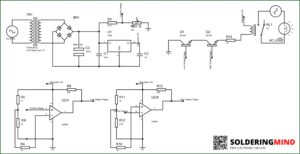
Circuit diagram

The External connector in the circuit can be used to connect more devices to the same signal stretching circuit. This can allow you to use multiple detectors even if they use different power sources and they can all share the common LED light. The LM358 dual op amp is connected in the standard connections.
This is a widely used configuration in the industry. In this circuit the positive supply for the op amp is coming from the 12v zener diode to provide fixed input voltage to the op amp IC.The negative supply is coming from the common ground.
Components required
| Components | Quantity |
| LM358 IC | 1 |
| 1N4007 Diode | 4 |
| 1uf/ 63 v | 1 |
| 1N4148 Diode | 2 |
| 12v Zener diode | 1 |
| BC639 ( NPN ) | 1 |
| BC640(PNP) | 1 |
| LED | 1 |
| R8 and R9 | see below table |
| 1K resistor | 5 |
| 100k resistor | 4 |
| 27k resistor | 1 |
Working of Q1 and Q2 Transistor and Selection
Q1 is a PNP transistor and Q2 is a NPN transistor. The two transistors detect the input signal from the audio. Under normal conditions there is no signal input the transistor Q1 always turns on. If the output signal from either channel gets close to the power supply voltage and matches with the reference voltage the PNP transistor turns off because the voltage at its base becomes higher than at its emitter.
The selection of transistors based on the amplifier power supply voltage. For most amplifier supplies it is around 42v dual supply. Then you can use BC547 ( NPN) and BC557 (PNP) transistors. If you are working with voltage up-to 70v then use BC639 and BC640 transistors.
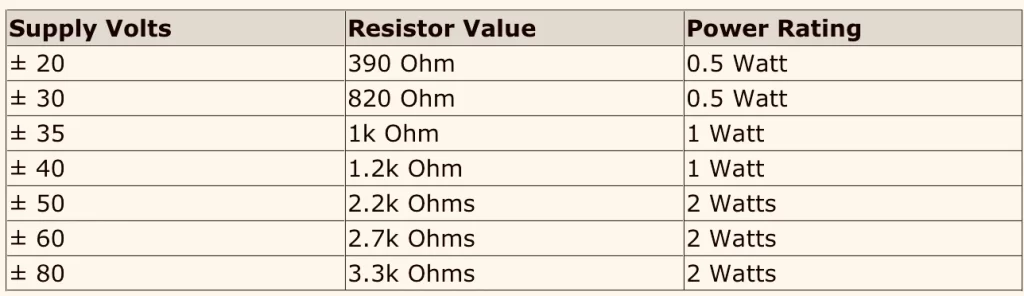
R8 Resistor selection
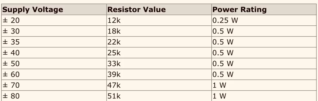
R9 Resistor selection
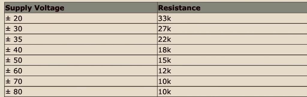
R10 and R11 Values
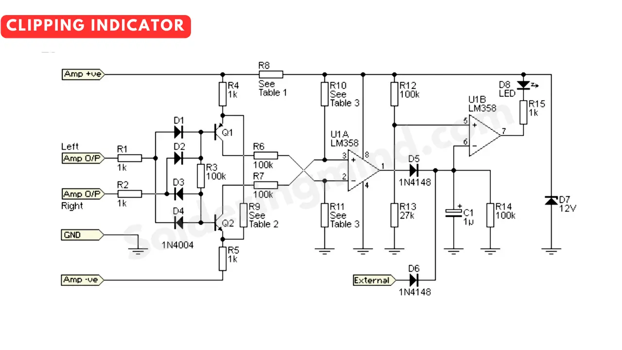
Working
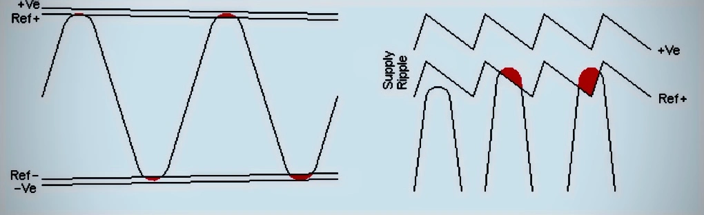
In the figure below the red area, in that point of output signal will trigger the detector. The detection voltage is comparing with the +ve reference voltage and turn on the clipping LED.
The same process is happening to the negative supply part of the circuit.
A common power supply unit is using for multiple amplifier circuit and you can add it into the clipping circuit. By providing 2 diodes and one 1k resistor. The led turn on if any distorted signal or clipping happens. This will protect the speaker and provide good music experience.