An Arduino microcontroller can be used to control a battery charging circuit, allowing for the monitoring and regulation of the charging process. This can be done by using the Arduino’s analog-to-digital converter (ADC) to measure the voltage and current of the battery, and then using that information to control the charging process.
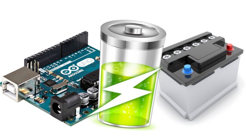
There are several charging algorithms that can be used to charge batteries, such as constant current constant voltage (CC-CV), Pulse width modulation (PWM) and 3-stage charging (Bulk, Absorption, Float) which are suited for different types of batteries. The Arduino can be programmed to implement these algorithms and monitor the battery status throughout the charging process.
For example, a simple charging circuit could consist of an Arduino, a battery, a voltage regulator, and a switch (such as a MOSFET). The Arduino would measure the battery’s voltage and current, and then use that information to control the switch and regulate the charging process.
It’s worth noting that a complete battery charging system should include many more safety features and protections, such as over-voltage, over-current, and short-circuit protection. Also, It’s important to choose the right charging algorithm and parameters for the specific type of battery being used to avoid damaging it.
An Arduino microcontroller can be used to control a battery charger circuit that charges a 12V lead-acid battery. The basic idea is to use the Arduino to monitor the voltage and current of the battery, and then use that information to control the charging process.
Here is an example of Arduino code for a simple 12V battery charger:
Copy the code and burn the code to your arduino board.
#define batteryVoltagePin A0 // Pin connected to the battery voltage divider
#define batteryCurrentPin A1 // Pin connected to the battery current shunt
#define chargePin 9 // Pin connected to the charge control

float batteryVoltage;
float batteryCurrent;

void setup() {
  pinMode(chargePin, OUTPUT);
  digitalWrite(chargePin, LOW);
}

void loop() {
  batteryVoltage = getBatteryVoltage();
  batteryCurrent = getBatteryCurrent();

  if (batteryVoltage < 12.6 && batteryCurrent < 0.1) { // if the battery voltage is below 12.6V and the current is below 0.1A
    digitalWrite(chargePin, HIGH); // turn on the charger
  } else {
    digitalWrite(chargePin, LOW); // turn off the charger
  }
}

float getBatteryVoltage() {
  // read the battery voltage and convert it to a voltage value
  return (analogRead(batteryVoltagePin) * (5.0 / 1023.0)) * 11;
}

float getBatteryCurrent() {
  // read the battery current and convert it to a current value
  return (analogRead(batteryCurrentPin) * (5.0 / 1023.0)) / 0.05;
}
This code uses two analog inputs, one connected to a voltage divider to measure the battery voltage, and another one connected to a shunt resistor to measure the battery current. The code reads the voltage and current values, compares them to some predefined thresholds, and then controls a switch (in this example, a pin connected to an external MOSFET) to turn the charger on or off.
It’s worth noting that this is a simple example, and that a real-world battery charger should include many more safety features and protections, such as over-voltage, over-current, and short-circuit protection. Also, this code assumes that the voltage divider is correctly calibrated and the shunt resistor is correctly sized and calibrated.
Also, it’s good to note that lead-acid batteries require a specific charging algorithm, called 3-stage charging (Bulk, Absorption, Float) to prolong the battery life and avoid overcharging, which this example doesn’t cover.


