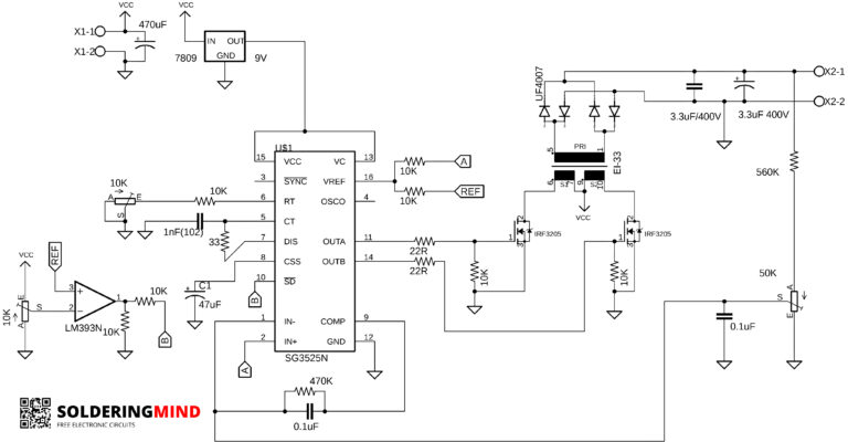
This is the most common inverter circuit based on the PWM ic of sg3525 and you will get a power output of about 500 watts will deliver. To increase the power of the inverter you need to use the larger transformer. for getting 500watts you need to use 12v 6 Ampere transformer.
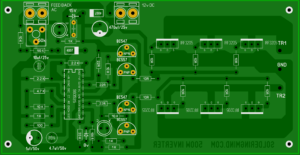
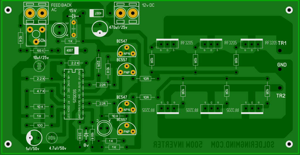
The sg3525 ic will oscillate at 100hz and the PWM output will be 50hz.
Download PCB layout HERE
Calculating oscillator frequency
To calculate the frequency of the PWM ic we are using an equation.
f= 1/CT(0.7 RT + 3 RD)
Frequency calaculation of sg3525
CT – the capacitor connected with the 5 the pin of the ic ( 1uf)
RT – The resistor connected to the 6 the pin and ground (15.7 k)
RD – the resistor connected to the 5 the pin ad 7 the pin (100R)
so, the oscillator frequency is,
= 1/ 0.0000010005 (0.7 * 15700 + 3* 100)
= 1/ 0.0000010005*11290
=89 Hz
almost 90 to 100 Hz we will get ( because the values of the components are equal to the calculated values)
So the oscillator frequency is 90 to 100Hz and the switching frequency is 45 to 50 Hz.


Hello everybody. Has anyone built this circuit? does it really work?
You are using 100mA Output Transistors why?The SG3525 have a push/pull output off 400mA,it’ s not make any sense!!!
Because for the safety and smooth working
i want to purchase tyhis sir plz help
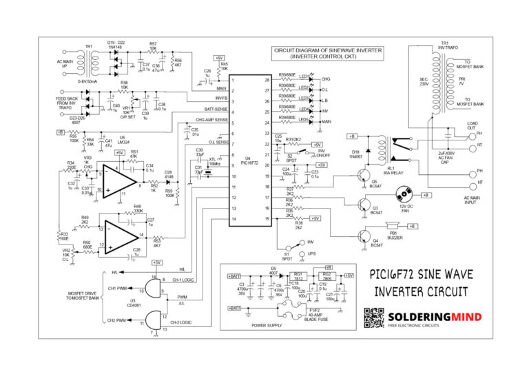
Who does know, what must be variable tension of feed-back of AC in this project?
Hii
Hi
Please little hint on integrating a charging and overload circuit
This is 104 ciramic capaciter to use better or not use no matter
There are two components with no values marked AC and a capacitor which looks like a ceramic under 15V zenor.please what are the values
Please little hint on integrating a charging and overload circuit?
please!can you show us the circuit diagram of this design.thanks for advance.
NO CIRCUIT DIAGRAM AVILABLE
Good morning sir,
Please sir i have a question on the capacitor 4.7uf 50v and 1uf 50v are they the same types of capacitor or they are different type???
please, can you send me in my email the circuit diagram of this design?thanks.