Building a 100 watt Amplifier can be highly rewarding because of several reasons. Most of the specific reasons are mentioned here. The High power audio amplifier can significantly improve the audio experience and provide the improved sound quality.
If you are building your own audio amplifier, it could be an excellent way to learn more opportunities in Audio amplifiers. In this article, you can learn about the circuit diagram, amplification principle, and how the electronic components are working inside the amplifier. DIY amplifier projects are mostly cost effective and you can get those components cheaply from the Electronic market.
I am planning to build a powerful 100 watt amplifier using Mosfets, So this instructions and guides will help the electronics enthusiast who are looking to build a MOSFET based Amplifier.
What are the benefits of a MOSFET amplifier?
The Mosfet based amplifier circuits offer several benefits, such as high efficiency in audio amplification. The Mosfet is also known as Metal oxide semiconductor field effect transistor, Which has low internal resistance and minimises the power loss and Heat generation. This will make the Mosfet are the perfect choice for audio amplifier making.
The second important thing is superior audio quality and high fidelity audio output. The high input and low output capacitance will contribute to load distortion and excellent linearity, which is important for the high quality audio sound reproduction, so the most we are able to provide the features.
The other things are thermal stability, high power handling, fast switching speed, and low frequency handling capacity. The mosfet is designed for high temperature working conditions and also with the fastest switching speed feature. Because the high power audio amplifier requires high voltage input and high current. So the most we can handle is the high power, current and voltage supply.
Mosfets are providing less noise distortion, High power output, Less heat generation, High voltage and current handling capacity and increasing the life of your Amplifier.
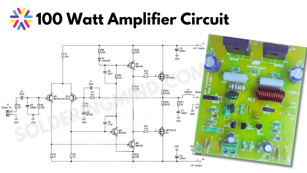
100 Watt MOSFET Amplifier Circuit
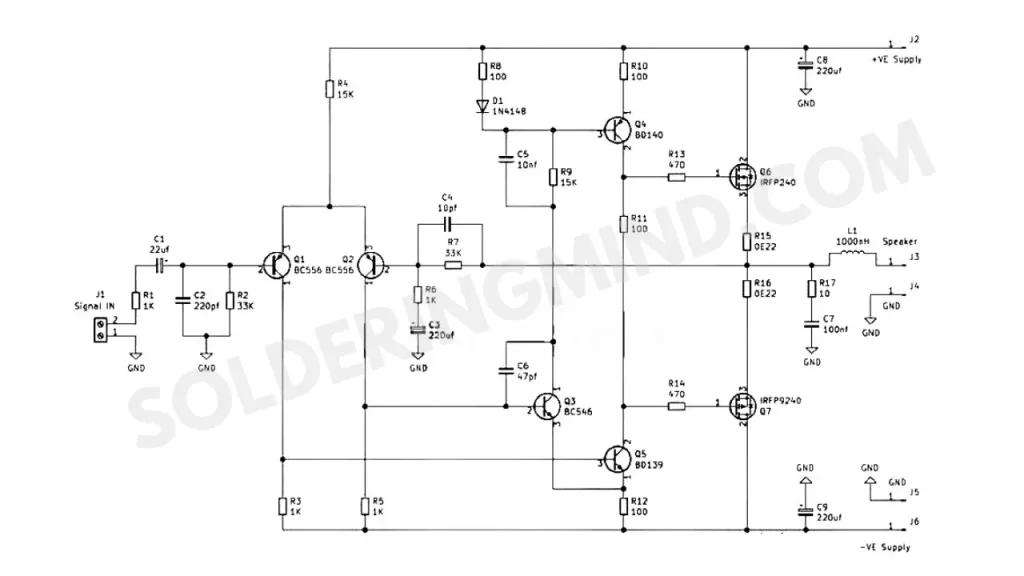
This Amplifier circuit is designed with few number of electronic components and suitable for electronic enthusiast. This circuit is working with a Powerful N channel and P channel Mosfets. The IRFP240 and IRFP9240, both mosfets are popular audio amplifiers circuits. These are the best choice for most of the PA audio amplifier system.
The other transistor of BC556, BC546, BD139 and BD140 are the cheap components available in any electronics components sales shops. So the availability of these components are very easy. Due to the structure of this given circuit diagram any electronics hobbyist can easily assemble it on bread board or a mini PCB.
Components Required
| Components | Value | Quantity |
|---|---|---|
| Mosfet | IRFP240, IRFP9240 | 1, 1 |
| Transistors | BC556, BC546, BD139, BD140 | 2, 1, 1, 1 |
| Resistors | 1k, 33k, 15k, 100R, 470R, 0E22/3watt | 3, 2, 2, 3, 1, 2 |
| Capacitors | 22uf, 220uf, 100nf, 220pf, 10nf, 47pf | 1, 3, 1, 1, 1, 1, |
| Power supply | 24-0-24 v DC | 1 |
| Inductor | 100uh coil | 1 |
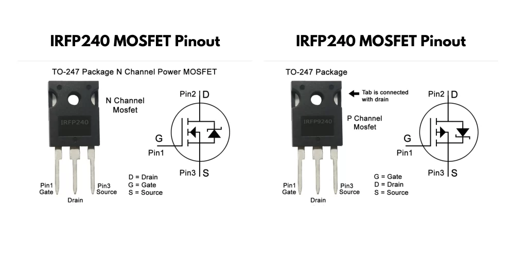
IRFP240 and IRFP9240 MOSFET Pinout
Working of MOSFET based Audio Amplifier
The IRFP240 and IRFP9240 are the P channel and N channel power MOSFETS respectively. The working of the audio amplifier consists of several stages, such as signal input stage, voltage gain stage, driver stage, amplification stage, output stage, feedback loop stage, and power supply section.
I am not going through the stages in deep, Just giving you the basic principle and working of this amplifier Circuit. The audio signal is gives to the input stage which consists of a coupling capacitor , which will block the DC input and allow only the AC audio signal to pass through it. After that, the input signal is fed into the transistor, which will pre amplifying the audio signal.
The Pre amplified Audio signal is reached to the driver section, which will boost the audio signal and provided to the power amplification stage. In the output stage, the combined MOSFET Circuit will amplify the small audio signals to 20 times or more stronger signals and it is sent through the inductor. The inductor is used to avoid unwanted frequency reaching to the speaker coil.