Solar mppt charge controller circuit diagram
hello our today topic is solar mppt charge controller circuit. if you are thinking about this project is small one. no way, the exiting electronic project will provide 12v – 24v 20amp DC voltage. so why are you waiting for, start to purchase the components from your nearest electronics shop and lets we start.
The circuit is working based on a single pwm ic of UC3845. It is a Single ended, 500KHz current mode PWM controller with 8.4V/7.6V UVLO 50% duty cycle, 0C to 70C. So you can able to see this IC in several buck control circuits.
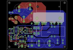
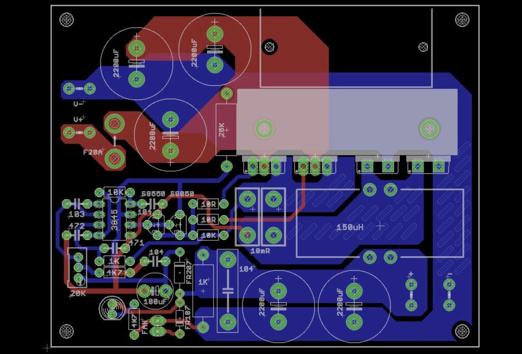
MPPT charge controller circuit pcb
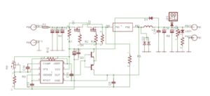
MPPT charge controller circuit diagram
Use mosfet of IRF4110 ( it has the capability to drive 80V dc ), the toroid core should be 50Uh winding with copper wire.


Can this buck mppt charger used for 18volt 80 watt solar panels to charge battery
Adjustment needed
This is a good project. But it is incomplete for a person who is about to make it. There are no images of the complete project. Only layout and circuit diagram. There are no details of coil and toroid etc.
India