Motion sensor circuit 220v
This is a very simple and low cost 220v AC motion sensor light circuit. This design using A PIR sensor and Transformerless power supply and a triac based control system. The power supply section completely working based on few components with high voltage rating ( above 220v AC ).
Caution: Extreme care is need when you are working with this circuit. All components are working in 220v AC so don’t touch any area of components while its working. Always cover the components when you are going to turn on the circuit. Keep some distance and keep safe while you are on work with AC circuits.
Ac Motion Sensor Light Working
The motion sensor working in 220v ac. The motion sensor module will turn on when any motion detected. Motion means any heat energy producing substance, Humans, pets..etc. When the object reaches the pir motion sensor range ( pre determined by the preset in the board ) the module will turn on and a potential difference will occurs in the output of the motion detector.
This output voltage will be around 3.3v DC. This is pretty much enough for triggering the relay or a triac. For AC circuit here using a BT136 Triac to switch the 220v AC bulb. The motion detected the light will turn on and waiting for the delay and return to power off state.
Motion Sensor Circuit Diagram For Lighting
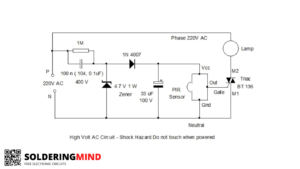
The PIR sensor have 2 mode. First one is movement detection and delay system is known as triggered mode and second one is re-triggered mode. Let me explain in brief. In triggered mode – when a object reached in the sensing area the sensor start to trigger, in that first trigger the supporting circuit start to function and turn the circuit for the delay time ( adjusted by preset ). The delay time can be set from 30 seconds to 3 minutes.
But in re triggered mode the circuit always keeps on and no delay timer has to be implementing. So if anybody reaches the sensing area the circuit turn on and it will turn off if the Person moves from the sensing area.
Components List
| 100nf capacitor ( 104 or 0.1uf 400v ) | 1 |
| 1M resistor | 1 |
| 4.7v/5.1v 1 watt zener diode | 1 |
| 1N4007 diode | 1 |
| 33uf /100v capacitor | 1 |
| PIR motion sensor | 1 |
| BT 136 TRIAC | 1 |
Triac BT 136 will drive the bulb. It can able to handle up to 250watt load. So the lamp can be a CFL, Tube, or LED lights. When the motion detects the signals goes in to the triac gate pin and allow the electricity passage from pin M1 to M2 then the lights turns off visa Vera’s.


I made this but when I get out from the range and delay time is finished, the light is not turning off. It is blinking. when I go to the range, it stable. but then again blinking if go out of range and delay time finished. only first or second time it was working perfectly. Why it is blinking?
No chance of blinking I’m using this circuit in my personal room its working perfectly