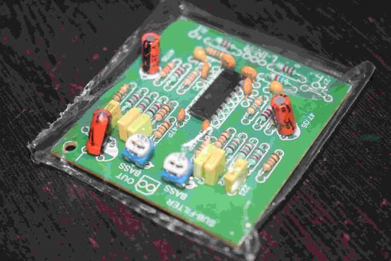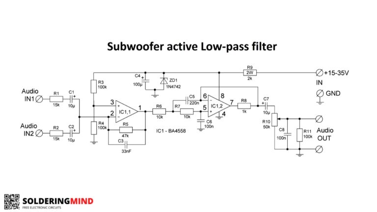
The NE5532 IC based subwoofer filter board can able to produce bass sound from the input audio signal. So the Low pass filter subwoofer is also known as Subwoofer Bass Board.
This Subwoofer filter board contains adjustable frequency and volume control Potentiometer for your convenience.
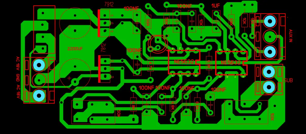
The PCB layout is designed neat and clean. You can use this design to build for your personal use only, Not for commercial purpose.
About Low Pass Filter Subwoofer Board
The 2 operational amplifier ( op-amp ) NE5532 is using here. The aux input IC section is working as an inverting amplifier.
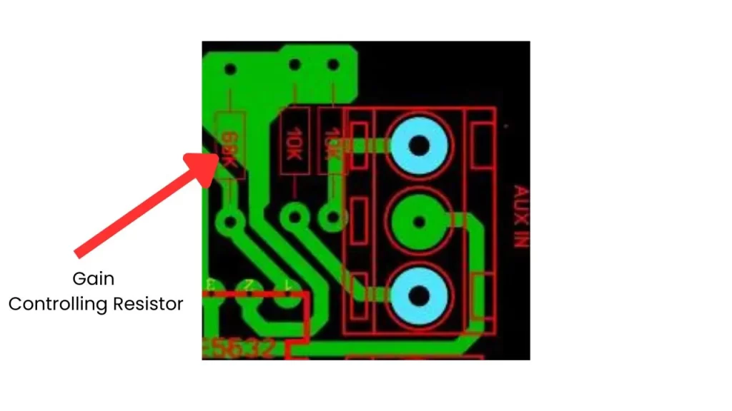
The gain will be 13.6, The 68K resistor is determining the gain. 1uf and 10K resistors are High pass RC filter in this circuit.
The cut off frequency is about 15.91Hz. The output of the circuit is set to cutoff frequency of 28Hz to 234Hz. this frequency range is pretty good for subwoofer working.
PCB Layout
Features of this Low pass subwoofer Filter Board
- Output frequency range of 28-234 HZ
- Adjustable frequency using Attached potentiometer.
- No need to add another volume controller to control the sub filter output.
- High quality operational amplifier using in this circuit.
- Efficient working performance.
- Input working voltage can be use from 12-0-12V AC to 27-0-27V AC.
- Terminal screw attached with this PCB to allow easy connection of wires.
FAQ
Low pass filter will filter out the high frequency and pass the low frequency of 28 to 200 Hz to the output.
The sub woofer is designed for working at low frequency range, So the low pass filter board is needed to work the subwoofer in its 100 percentage efficiency.
Subwoofer is LPF means producing high response at low frequency range.
This is the delay function of input audio signals. Suitable for based on your rooms.
80 Hz is the perfect frequency for the subwoofer to work.
The frequency range of 20 to 200 Hz is for customer products. Below 100 is professional sound system and frequency below 80 is thx certified system.


