LA4508 IC is a AF Power amplifier and it can deliver the output of 8.5 watts in dual channel at 3 ohms speaker. The IC has the main features of Low idling current of 20mA in through both channels. The high ripple rejection rate is about 60dB at steady state. The s acceptable pop noise will arrive when your turn on the power supply. The good advantage is about the internal thermal protection system on it, so the life of this audio amplifier will last long. Through this entire article lets check out LA4508 audio amplifier circuit details.
Characteristics of LA4508 IC
- Maximum supply voltage – 24v DC
- Allowable power dissipation on both channel is 15 watts
- The maximum output current is 2.5A
- The recommended power supply is 15V DC at 3 ohms load.
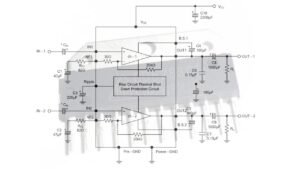
LA4508 Audio amplifier circuit diagram

Also Check : Other best audio amplifier circuits
Components required
- LA4508 Audio amplifier IC
- 220uf, 100uf, 1000uf capacitor with voltage rate of 16v
- 0.01 uf capacitor
- 0.15uf capacitor
- DS130T Diode
Additional information
Decoupling capacitor : The C1 220uf/25v capacitor is known as decoupling capacitor in the circuit. The capacitor is using as the pop noise preventer while you are power on the circuit.
The C2 and C3 capacitors are feedback capacitors are determining the required bandwidth in the circuit and this one also affecting the starting time of the audio amplifier.
C4 and C5 are ceramic capacitors with rating of 0.01uf. These are used to reduce the distortion in the circuit while a high frequency over input time.
Their is a chance to pin to pin short circuit, so more care need while you are working with LA4508 IC. When the pins of the IC shorted the Breakdown or deterioration will occur if you are applying supply voltage in to it.
Also Check : 400 watt class D amplifier circuit and PCB Layout


May I get the full project and the simplified circuit diagram for the LA 4508 amplifier