How to test IR2153 IC Before using in Class D Audio Amplifiers
Testing IR2153 IC is very important when you put the IC in a class d audio amplifier circuit. Before connecting the amplifier circuit you need to analyze whether the IC works properly.
The damaged IC or malfunctioning will kill the external components and Mosfet of the Class D amplifiers. Make sure that the output of the IC oscillates or not. This can be done by using a simple tester circuit.
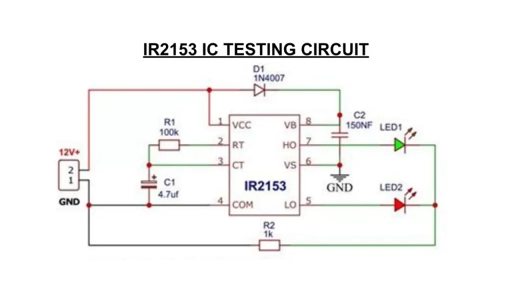
This tester circuit will check the dead time of the IC and confirm whether the output signals are working correctly or not.
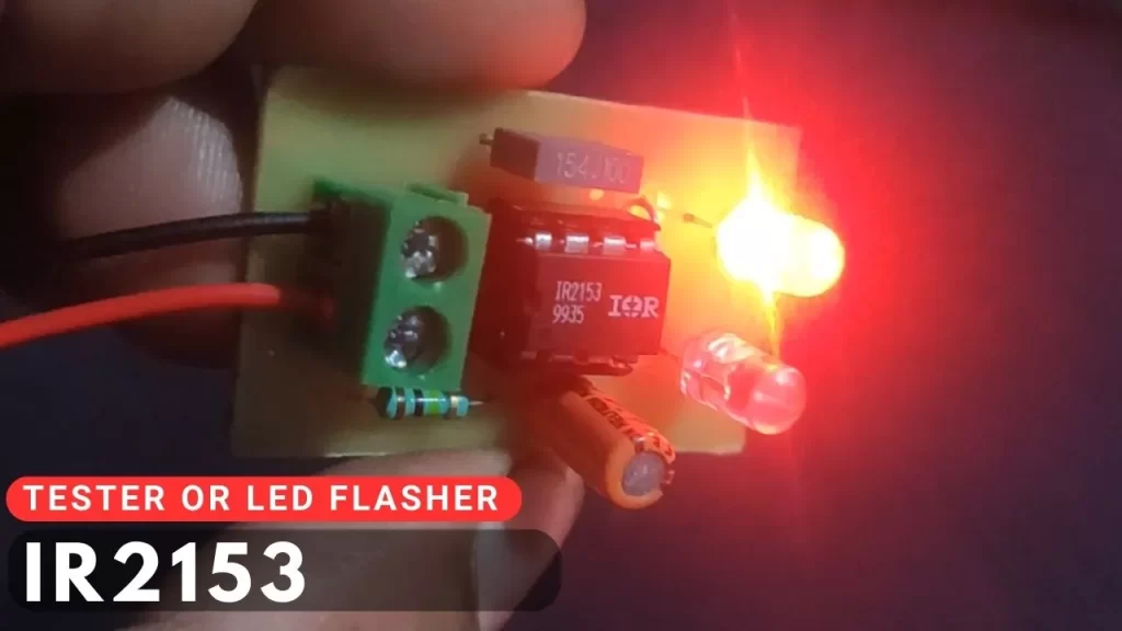
The IC working is confirmed based on the blinking LED in the circuit. The 2 LEDs are on and off one by one, this means the one output pin turns on and at the same time the the second output pin turns off the second LED.
The testing of the IR2153 will be very useful for diagnosing the other issues in the class D amplifier too. If the Class D amplifier Is getting hot or the speaker burns out the coil, that time you need to pull out the IC and check using this tester circuit.
IR2153 IC Tester Circuit
Components required
| Component | Value |
|---|---|
| IR2153 IC | 1 |
| Resistors 100K, 1K | 1, 1 |
| Capacitor 4.7uf, 150nf | 1, 1 |
| LED and connecting wires |
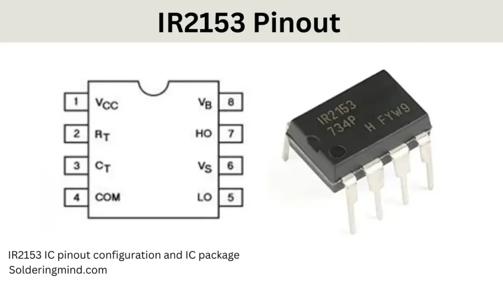
Pinout of IR2153
PCB Layout
The resistor value of 100kΩ (RT) and a capacitor value of 4.7μF (CT) are the timing components for the IC’s operation, especially for dead time and frequency adjustment.
The frequency of the oscillator can be estimated using the formula:
f=1/RT×CT×0.7
Plugging in your values:
- RT = 100,000 Ω (100kΩ)
- CT = 4.7 × 10^-6 F (4.7μF)
f= 1/ 1100,000×4.7×10−6×0.7≈3.02 Hz
The IR2153 is an half bridge oscillator IC. It can be using in the SMPS circuit and class d amplifier. I found this IC in 400 watt class D amplifier Circuit. The IC is built for an integrated 600v half bridge gate driver to operate the transistors or Mosfets.
The IC has tighter initial deadtime control. The IR2153D is the improved version of IR2155 and IR2152 IC. Testing IR2153 IC is essential before inserting it to the circuit or PCB. Because lot of IC are not working properly sometime the IC doe not produce any output at their pin number of 5 and 7.
Building Testing circuit is very simple and it needs few components. The same testing circuit can be use as a LED flasher or LED Blinking.

