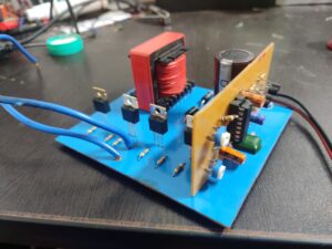
The power inverter is based on the ic SG3525 PWM. The circuit is not complex which is very easy to build. working on this board is very pretty. The heat dissipation is very low. The working frequency is 30-60Khz.
High Frequency Inverter
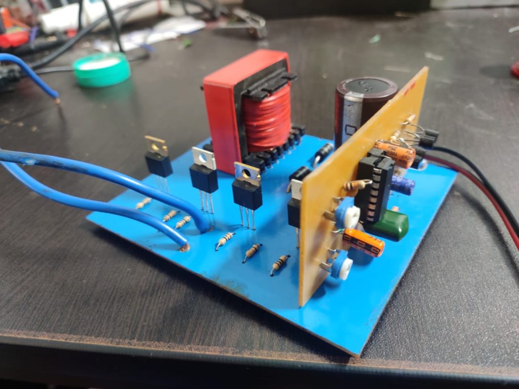
The power inverter board contains two different boards. The first one is a power board which consists of a transformer, the transformer is not an iron core transformer. the ferrite core transformer which working under the situation of frequency in kilohertz.
Transformer Coil Winding
The transformer made up of medium type of ferrite core transformer ( The number is Not mentioning: you can use any core suitable for the layout). The coil wind contains a primary and secondary, the primary winded with 19SWG copper wire with two layer and center tapping at each 4 turns.
Then the next one is the secondary coil winding you need to cover the entire primary coil using insulation tapes to avoid the short circuit. The secondary coil need 100 turns minimum to produce 230-400v Dc. The gauge of the copper wire is 22 swg.
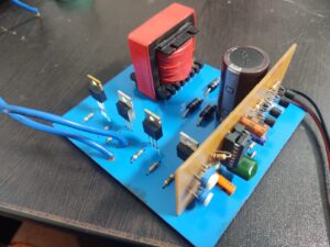
SG3525 PWM generating Module
The second board is the PWM frequency generating board. which provides the pulse frequency to the MOSFET drive then the MOSFETs get to start to switch at a higher frequency.
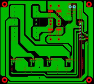
SG3525 inverter circuit PCB


Nice to hear
Thanks
Hello pleas shematic circuit
Diagram pcb inverter
can you send me the sch and pcb for SG3525 inverter circuit pcb on sprint layout software