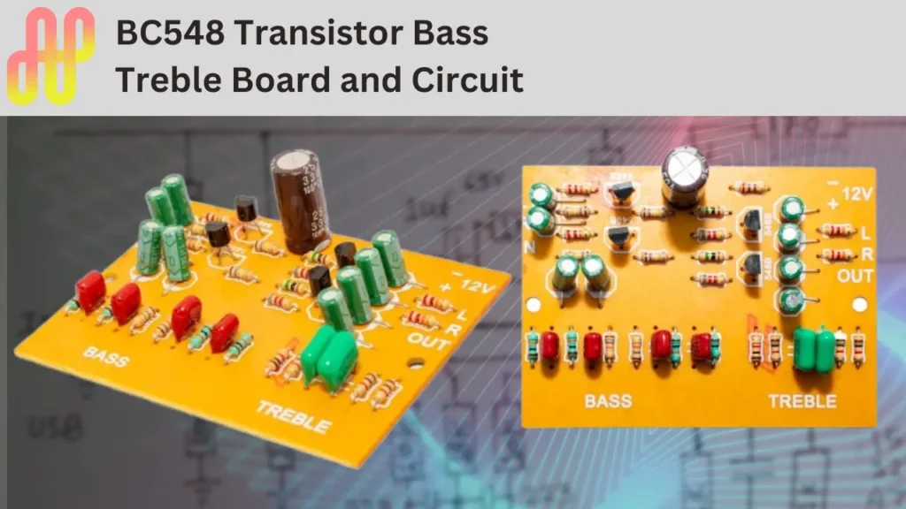
This bass treble board is now available in the local market of India. It is the most popular and high-performing bass treble circuit designed with a few electronic components.
BC548 is a low-power NPN transistor used to control the bass and treble of the incoming audio signal. The main feature of this board is that a single power supply is needed to work this. Most audio amplifiers work with a 12V DC supply, so the circuit helps control the Bass and Treble.
BC548 Transistor Bass Treble Board
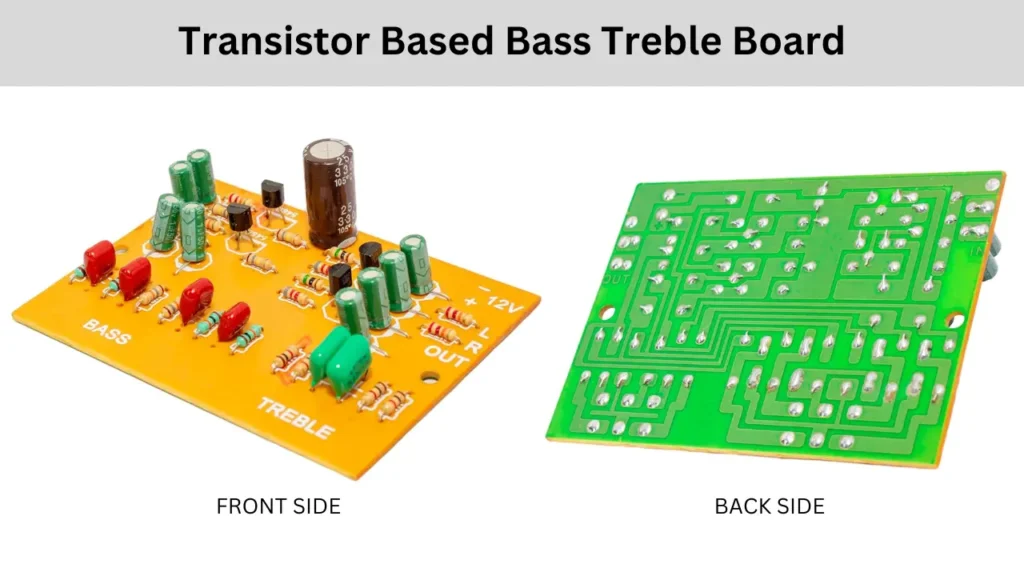
This board is not available in most of India or other countries. In this situation, the circuit diagram and PCB will help you redesign the circuit.
If you want to build a stereo bass treble circuit you need 2 pairs of BC548 NPN transistors. In this circuit diagram, I’m giving the single-channel circuit, to make it stereo-build the same copy of the circuit two times. One for the Left and one for the Right channel of the audio signal.
BC548 Bass Treble Circuit Diagram
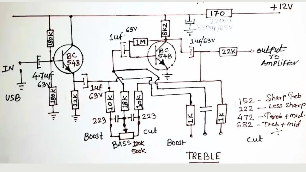
Circuit Explanation
The stereo amplifier needs the stereo audio inputs such as Left channel and Right channel. To control the bass and treble of these separate channels, you need to build the same type of bass treble circuit on each channel.
The BC548 NPN transistor is used to control the Bass and treble. However, the first transistor is used for gain boosting, which means input signal boosting. The second transistor does the job of controlling the bass and treble by adjusting the connected potentiometer.
Connection
The 12V DC supply is connected with a 220 ohms or 270 ohms resistor and a filter capacitor of 330uf to avoid noise. The input signal is fed to the first transistor base pin using a filter capacitor to block the DC voltage, the capacitor value is 4.7uf/63v.
A voltage divider is made in the base pin of the first transistor, and a ground-connected resistor is 180k, and the base to positive is the same. The second BC548 transistor collector pin is connected to a positive supply with a resistor value of 8.2K ohms.
The second transistor is biased with a high resistance value resistor of 1M. The signal is taken from the potentiometer center pin using an 18K resistor and 1uf electrolytic capacitor. we get the audio output from the collector pin of the transistor. A 10k resistor is used in the third pin of the potentiometer to cut the bass. For the perfect Bass filtering a 223pf capacitor is used in between the resistors.

