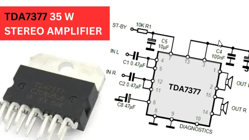
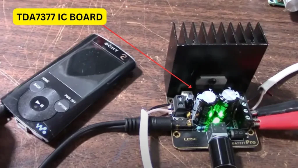
Building a car audio amplifier circuit is not a complex process. Many ICs are available on the market, and they typically require only a few number of external components to work. One of the popular choices is the TDA7377. This car audio amplifier IC operates on a DC supply of 12 to 18 volts. The quality of the sound is nice. The TDA series of ICs are commonly used in audio amplification. Let’s take a closer look at the circuit diagram, pinout, and additional information about the TDA7377 IC.
TDA7377 IC Pinout Configuration
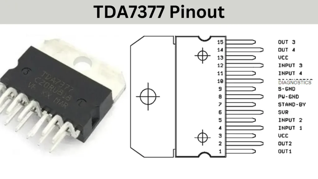
| Pin Number | Pin Name | Description |
|---|---|---|
| 1 | OUT 1 | Output 1 |
| 2 | OUT 2 | Output 2 |
| 3 | VCC | Supply Voltage |
| 4 | IN 1 | Input 1 |
| 5 | IN 2 | Input 2 |
| 6 | SVR | Supply Voltage Rejection |
| 7 | ST BY | Standby |
| 8 | PW GND | Power Ground |
| 9 | S GND | Signal Ground |
| 10 | DIAG | Diagnostics |
| 11 | IN 4 | Input 4 |
| 12 | IN 3 | Input 3 |
| 13 | VCC | Positive Supply Voltage |
| 14 | OUT 4 | Output 4 |
| 15 | OUT 3 | Output 3 |
Features of TDA7377 IC
- High output power capability of 2×35 watts at 4 ohms speaker.
- This IC can use in different configurations such as stereo bridge mode or 4 channel audio system.
- Stand by function.
- Few number of external components needed.
- No Pop up sound during stand by operations.
- Class AB high quality audio output.
- Operating supply voltage 12 to 18V DC.
- Built in short circuit protection.
35 Watt Stereo Amplifier Using the TDA7377
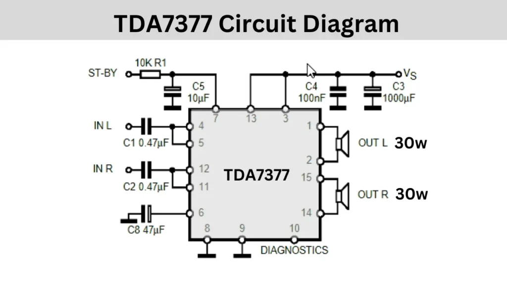
Components Required
| Components | Quantity |
| TDA7377 IC | 1 |
| 0.47uf, 47uf, 10uf, 100nf, 1000uf Capacitor | 2, 1, 1, 1 ,1 |
| 10k Resistor | 1 |
The pin number 4 and pin number 5 are connected together and are connected to the 0.47uf electrolytic capacitor. This capacitor at the other end is connected to the input audio source. The same is happening on the pin number 12 and 11. The 6 th pin of the IC is grounded using a 47uf capacitor. The pin number 6 is a Supply voltage rejection pin of the IC.
10uf and a 10 k resistor is connected to the Stand by pin of the IC. The input voltage supply is well filtered by the help of a 1000uf electrolytic capacitor and 100nf disc or box type capacitor.
The amplifier output will be in bridge mode so connect the speaker connections directly to the IC output pins. The speaker connections are pin 1 and 2 the second speaker connection is Pin 15 and 14. You must connect a 35 watt 40hms speaker or woofer for this circuit.
Related Audio amplifier Circuits
- TDA7850 Amplifier IC Pinout and Circuit Diagram
- TDA7379 IC 38Watt Stereo Amplifier Circuit
- TDA1554Q: 4 x11 Watt IC Pinout and Technical Specifications
FAQ
The TDA7377 car audio amplifier IC typically provides an output power of around 35 watts per channel when operating in a bridged configuration. In a quad configuration. The exact output can vary based on the supply voltage and load impedance of the speaker.
TDA7377 is a quad amplifier for car audio amplifier IC with low distortion. TDA7297 is a dual amplifier for both car and home applications with high distortion comparing with TDA7377 IC.