
Are you looking for a mini voltage controller circuit? Yes, the perfect circuit for controlling the voltage from 0 to 60v DC circuit is here. The main advantage of this circuit is the minimum number of electronic components and effective way of voltage controlling. Let’s check out the details here.
Introduction
The 0 to 60 v dc controller will help you in most situations such as different equipment operation and also the testing of electronic circuits or DC motors. The controller is provided in the circuit when you rotate the potentiometer the DC output voltage gets lowered and rotating it clockwise the output voltage is increased.
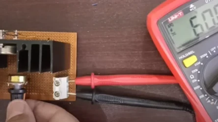
This circuit is very useful for studying the working of potentiometer and transistors. You can learn how it can work. But you need to measure the voltage correctly before connecting any electronic circuit to this circuit. The Other option is connect a 60v dc monitor display to check live voltage at the output.
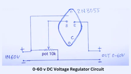
0-60V Adjustable Voltage Regulator Circuit
Components Required
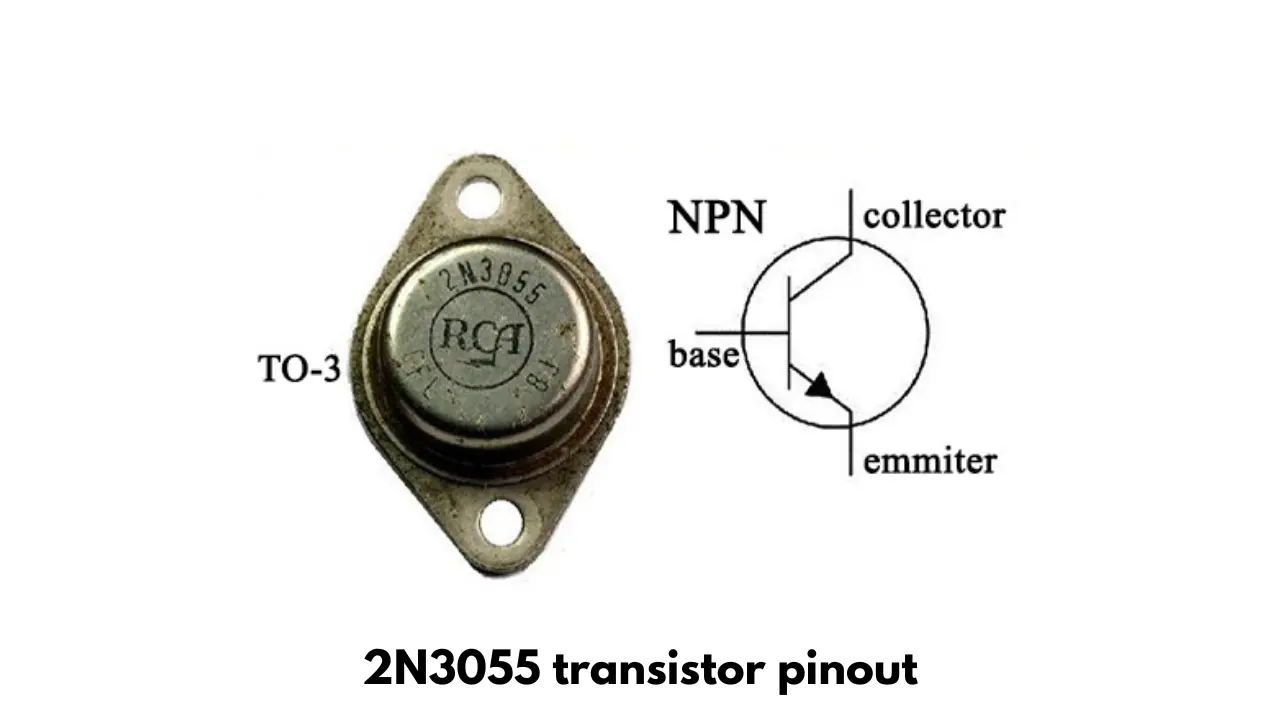
- 2N3055 NPN transistor.
- 10K potentiometer.
- 60V DC input from DC source.
- Output connector.
- Soldering iron and other useful Tools.
Testing of Circuit
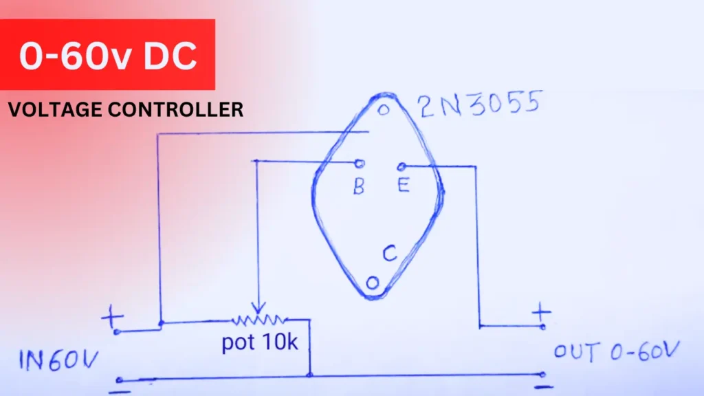
The circuit diagram is given above the paragraph. Connect the potentiometer center pin to the base pin of the 2n3055 transistor; the left pin of the 10k pot will connect with positive voltage and also with the body of the transistor.
The body is the collector pin of the transistor, the ground pin is common and the output DC voltage is taken from the emitter pin of the transistor.
When you rotate the towards the positive supply more voltage is passing through the transistor and the opposite will happen when you rotate it towards the negative connection of potentiometer.
