The Voltage-controlled amplifiers are electronic amplifiers that will vary their gain depending on the control voltage (CV). For more clarity, the processor will alter the amplitude of the signal proportional to the control voltage applied to its amplitude modulation.
The VCAs have many applications such as that are listed below.
- Audio level compression
- Synthesizers
- Amplitude modulation
Explanations

Lets to understand how the VCA works. From the name, it is clear that the amplification factor of the amplifier is controlled by the voltage. For the explanation we are taking an op-amp and we are using a noninverting mode like the Vin applied on the positive pin and in the negative pin of the op-amp we are connecting the feedback resistors.
R1 and R2 resistors are connected series from the Vout to the ground and the middle connection Vin 2 is connected. The fundamentals of electronics say that the Vin2 is an equation with the voltage divider resistors of R1 and R2.
Vin2 = Vout *R2/R1+R2
As comparing the Vin1 and Vin 2 there is a small difference in the voltage so we can replace the Vin 2 with Vin1. so the equation is changed to,
Vin1 = Vout*R2/R1+R2
And,
Vout/Vin = R1+R2/R2 that is equals 1+R1/R2
This equation solves that Positive quantity which is known as non inverting amplifier.
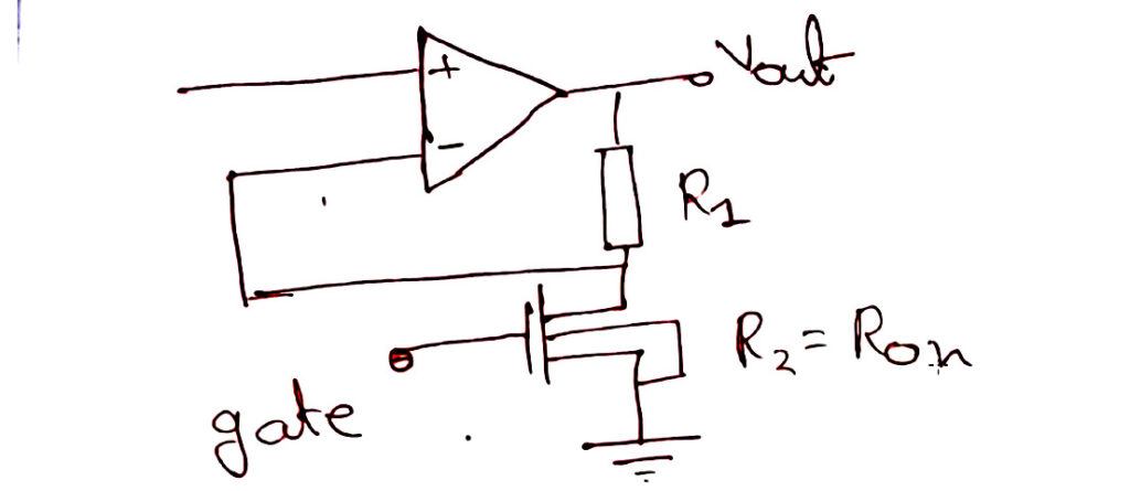
Ok, this is the common circuit basics you know, in VCA the R2 resistor is replaced with the Mosfet. So the R1 depends on the voltage given to the gate potential. If the gate-source potential the resistance R2 decreases and the overall gain increases. as per the equation 1+R1/R2. So this type of operational amplifier is known as a Voltage controller amplifier.