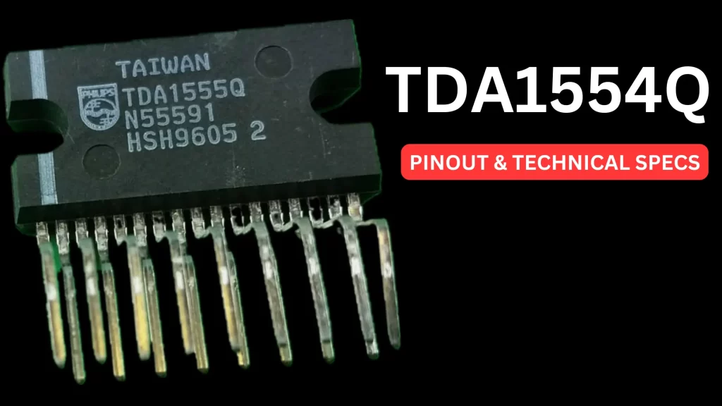
The TDA1554Q amplifier IC is mainly designed for high quality audio signal amplification. This quality of sound amplification is based on the type of electronic circuits or electronic components we are using. In this article I am going to discuss the quad bridge car audio amplifier IC of TDA1554Q. This is an integrated circuit suitable for stereo audio amplifiers. This specially designed audio amplifier IC is a combined class B output amplifier with 17 lead single in line plastic power packages. It is mainly used for car radio applications.
Introduction to TDA1554Q
The 17 pin audio IC can deliver the output in two different ways because this IC circuit can be bridge. In single end mode it can deliver up to 11 watts on each channel and 22 watt output power if you are using this IC in bridge mode.
If you are planning to build a 4 speaker system for your car the TDA1554Q IC based circuit is the best option for you. The Car DC supply line may deliver the DC voltage up to 18V DC, to overcome this issue the IC is designed with maximum input voltage up to 18V.
Features of TDA1554Q IC
- Perfectly designed for car audio amplifier system
- Only require few number of external electronics components
- The IC comes with Quad amplifiers
- Maximum output watts
- Stereo mode each channel deliver up to 22 watts at 12V DC
- Fixed gain of 20dB
- Thermally protected and in built reverse polarity safe
- No switch ON or OFF plop sound on speaker
The amplifier chip can work as a 4×11 W single-ended or 2×22W double ending power amplifier. TDA1554Q consists of four (quad) audio amplifiers with different inputs which comprises two inverting and two non inverting pins and because of this feature we can use it in single ended or bridge mode configurations. The gain of four amplifiers inside the IC is fixed range at 20dB.
One of the main features of this device is its mute/standby switch and this feature is important as it is used for manipulating the power supply to speakers. This device is very easy to use because of its flexible leads. Some of the other features of the devices are its high input power, fixed gain, thermal protection etc.
Pinout Diagram

Amplification Modes
- Single Ended Configuration (4x11W)
- Bridge Mode Configuration (2x22W)
Single Ended Configuration (4x11W)
In the single ended configuration of the circuit, the pin number 1, 2 17 and 16 is used for the four audio signal input pins. Then the output pins will be the same output pins of each amplifier circuit inside of this IC. The output pins of the IC are pin number 6, 8, 12 and 10. Pin number 5 and 13 is connecting to the positive supply of the car battery, and the 7 and 11 goes to the metallic body part of your car or negative supply.
Bridge Mode Configuration (2x22W)
In bridge mode the input pins of pin number 1 and pin number 2 are directly connected and signals are injected via a 220nf disc capacitor. The same is happening in the pin number 17 and 16. This type of configuration is for amplifier bridging. The output of the amplifier is the main output of each audio amplifier.