
This is a very simple and easiest circuit of a digital voltmeter. This circuit is working based on a PIC Microcontroller. So lets start PIC16F676 Programming for Voltmeter.
Because of the cheap price and large availability of this PIC microcontrollers are very popular in most of the branded electronics board. so don’t worry about the coding, while i am posting PIC-based projects with code only. so you can easily build and program it.
One of the most impressive advantages of this PIC16F676 IC is its internal 10-bit ADC ( Analogue to digital converter ). This will help us to convert our analog data into digital one. This PIC Microcontroller-based project works with a maximum input voltage of 30v DC.
This circuit diagram is very efficient and you can use it in any voltage-measuring devices. The accuracy of this circuit is determined by the 47k resistor and 10K trim pot, by changing this value you can adjust to the accurate values.
Circuit Diagram
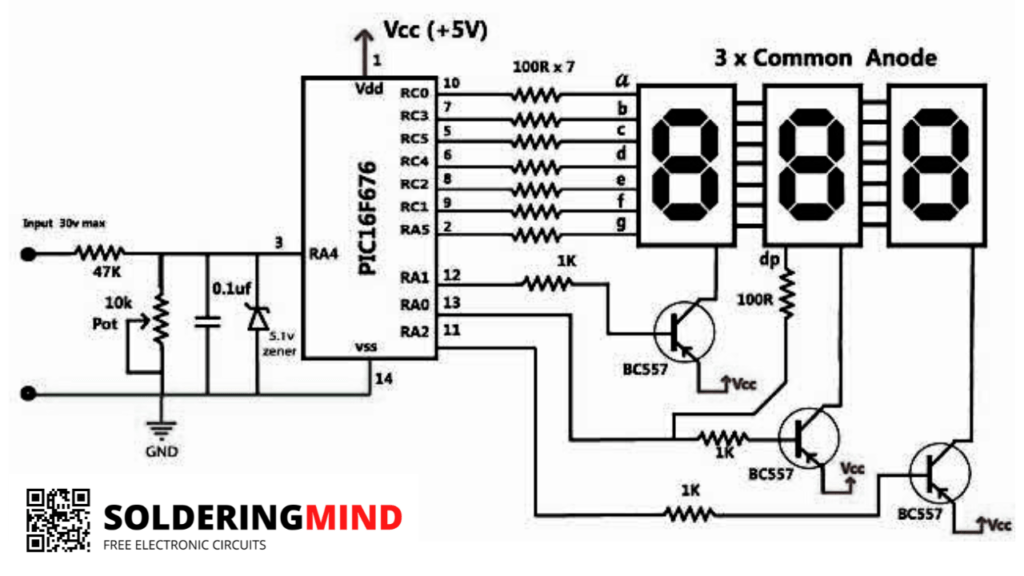
The input voltage of this IC is 5v DC voltage so you need to attach a 7805 regulator ic with this circuit for PIC microcontroller protection and also for the constant voltage maintenance.
The seven-segment display is used as an anode type. Three common anode displays are attached properly. and it is powered by the BC557 transistor. The working hex code is also available to download, so you can easily download and install the code to your Microcontroller IC.
For programming you need a PIK KIT programmer, if you are hearing this word first time check in internet about PIK kit programmers.

Can you provide a code
I need this volt meter Hex file
preciso de um votimetro de ttres digitos sete seguimentos com tres ditos
I need. To. Digital volt amp meter. Programing software. Need. Plz. Contact send me. Number. Delhi.
Upload soon stay connected with website