The LED flasher circuit is using in many situations such as alert, decorative lighting, Testing and debugging, and also the signal transmission. The CD4011 IC based LED flasher is designed with minimum number of external components and easy to build any electronics enthusiast.
The flasher circuit means the LED gets on and off at particulate time, this time should be a fixed and regular. Most of the LED flasher circuit is build with the common NE555 timer IC but this special circuit is designed with the popular NAND gate IC CD4011.
CD4011 IC Based LED Flasher Circuit

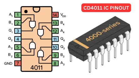
The CD4011 is a dual quad input NAND gate IC, which means the IC designed with one or more NAND gate which are the fundamentals of digital electronics. These gates are universal gates that are AND, OR, NOT, etc. To create an LED flasher circuit you can use one of the NAND gate to turn on and off the transistor.
CD4011 IC Pinout

The connected 2N3904 NPN transistors will turn on and off the connected LED. When the signals received from the CD4011 IC it will turn on and OFF. The transistors are working here as the fast switching actions.


