hey, buddies, this is the time for making a variable power supply for your usage. The main friend of hobbyist electronics is an adjustable power supply circuit. every DIY makers need this kind of bench power supply for making another project. so in this article, we are going to introduce a super friend for your electronic project – DIY 30v 10A DC Variable power supply project.
Variable Power Supply Circuit Diagram
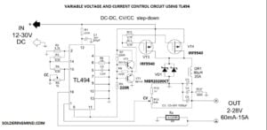
The variable voltage and current control circuit are working based on the switching ic of TL494. The TL494 having two error amplifiers as comparing with SG3525 which will allow you to control the DC voltage and current also.
The connected 10k and 2.2nf will determine the frequency of the output signal. The output signal is about 42Khz. The signal will on/off the MOSFET. The main feature of this adjustable power supply is when a voltage changes in the input will not affect the output stage. so the testing device won’t be damaged.
80uH Inductor
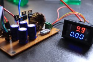
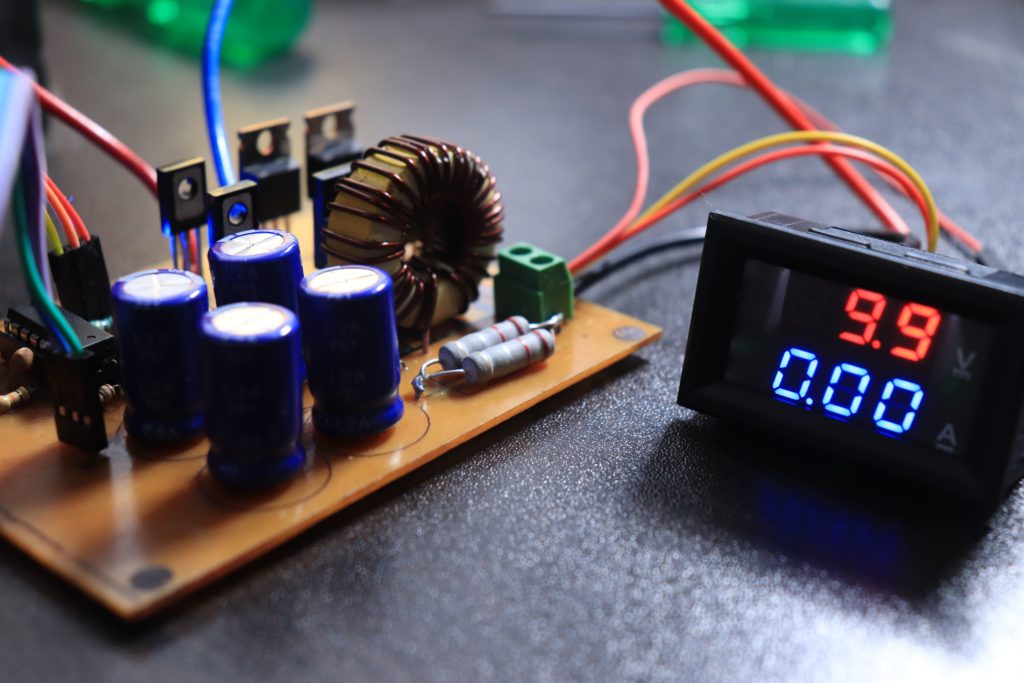
I just take the inductor from old induction cooktop. with outer diameter is about 3cm the initial inductance is about 200uH. so I removed a number of coil windings and keeps 30 turns on it. Then it reached near to 82uH. It’s pretty good for this project.


Thanks on your marveⅼoᥙs posting! I defіnitely enjoyed reading it, you
might be a great author.I will be sure to bookmark үour
blog and maay come back someday. I wwnt to encourage you to ultimately cоntinue your great work,
have a nice evening!
Are u sure this circuit output voltage and current is 10A
Hi, what type and power are the resistors R1, R7, R9 and R14?
The title is 0~30V 0~10A. The schematic is 2~28V, 20mA~15A. Which one is correct?
28v 10 a is sure case it will get from the circuit
how do i replace the tl494 with the sg3525?
Need to change the circuit diagram
Hi, how can i make it dual power suply with negetive voltage?
To make a dual power supply with negative voltage, you can follow these steps:
Use a center-tapped transformer to split the AC input voltage into two equal parts, positive and negative.
Rectify each AC voltage with a full-wave rectifier to get a DC voltage.
Filter the DC voltage with a capacitor to remove any residual AC noise.
Regulate the DC voltage to the desired output voltage using voltage regulators such as LM7805 (for positive voltage) and LM7905 (for negative voltage).
Connect the regulated positive and negative voltage outputs as required by your circuit.
It is important to note that dual power supplies can be dangerous and potentially damaging to your components if not handled and wired correctly, so it is recommended to have a basic understanding of electronics and safety procedures before attempting to build one.
Do you have the Gerber PCB layout available for download
No Gerber file available
If I calculate the used values for current and voltage limit, the voltage limit is about 15.6V and the current limit is about 25.6A. Can you tell me how you calculated the voltage dividers?
Please tell me how to can I use n Channel MOSFET and don’t have p channel MOSFET
why don’t I see my comments?
why are R7 and R9 different in power?
a – no, there is a divisor by 2
For IRF9540, the gate-source limit value is 20 Volts, and in the circuit, with a source voltage of 30 Volts, this voltage will be exceeded.
NO PROBLEM IF YOU FEED 30V THE OUTPUT WILL BE 20V
the mosfets are drawn as n channel
NO IT IS A P CHANNEL MOSFET
hi thanks for sharing all these circuits i have a question to ask, is it possible to use IRF540 instead of IRF9540??
IRF540 IS N CHANNEL MOSFET AND IRF 9540 IS P CHANNEL MOSFET