BLCD motor control circuit – In this article, I would like to share a very informative topic and circuit diagram for your salvaged hard disc drive spindle motor. Most electronic hobbyist thinks that such hard disc drives and spindle motors are good only in very specific situations. before we going to start this, first you need to know about the Hard disc Motor and how it works.
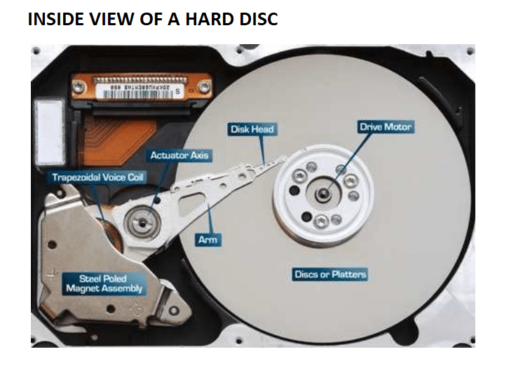
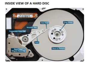
The hard disc drive (HDD) spindle motor, is a sensor-less three-phase brush-less DC (BLCD) motor.
What is a brushless DC motor? BLCD motor
in simple the brushless DC motor means it has not a brush like ordinary DC motors. this is a three-phase motor or three coiled motors with changing magnetic field. the magnet will be the rotor. The motor rotation is achieved by charging the direction of the magnetic field-generating coil. Then the rotor is a permanent magnet to control the rotation, we need to adjust the magnitude and current from the stationary coils.
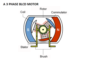
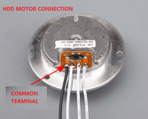
The brushless motor has three stationary coils with 6 wires from the coil. The 3 wires are internally connected and are taken as a common input. The remaining three wires are taken outside to give the supply. also, note that the three-phase DC motor needs three hall sensors to detect the position of the rotor.
Wiring of HDD BLCD motor?
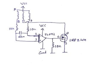
You noticed in a hard drive the motor has four input wires or input connections. and the wires are represented as A, B, C, and D. A, B, C are the three-wire output of the three coils. D represents the common wire that is internally connected.
How to run a 4-wire BLCD motor?
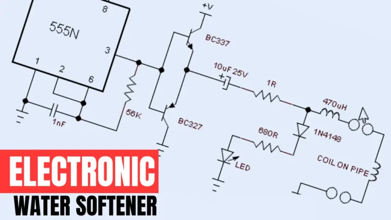
To rotate the BLCD motor we need to control the direction and the timing of the current in the stator coil. the circuit diagram shows the detailed connection of the project.
BLCD motor control circuit
