Most electronic circuits need proper voltage to work life long. Because too much input voltage greater than the standard recommended voltage will damage the electronic components. So to avoid this problem I am introducing the 9V DC Regulated power supply circuit.
Introduction
Always ensure the use of an appropriate current limit when powering sensitive components. A regulated power supply converts unregulated AC to a constant DC, ensuring that the output remains constant even if the input voltage changes.
Typically, a regulated power supply includes knobs to select both a current limit and a voltage. When a load is connected to the power supply outputs, it strives to maintain the chosen open circuit voltage across the load.
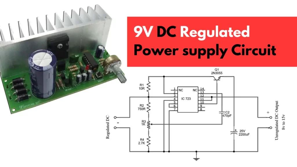
The current will continue to increase until the selected current limit is reached. At this point, the voltage across the load equals the chosen current multiplied by the load impedance. In this context, we design a 9V regulated power supply using the renowned linear regulator ic 723.
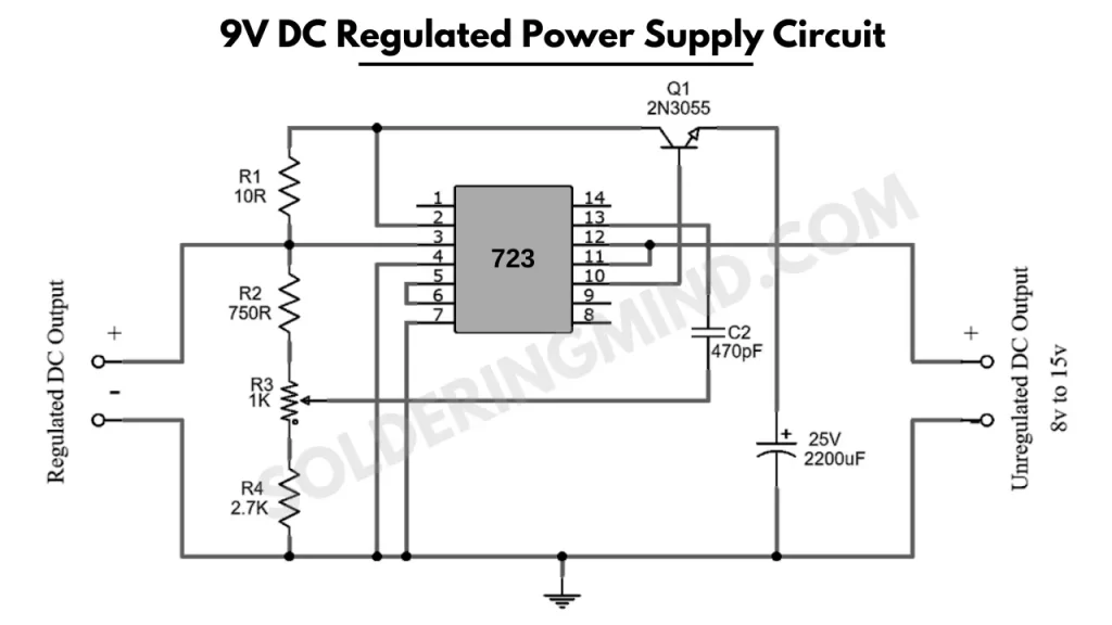
9V DC Regulated Power Supply Circuit Diagram
Components Required
| Components | Value | Qty |
| 1 | IC 723 | 1 |
| 2 | Transistor 2N3055 | 1 |
| 3 | Capacitor 2200uF/25V, 470pF | 1, 1 |
| 4 | Resistor 2.7K, 750Ω, 10Ω | 1, 1, 1 |
| 5 | Variable Resistor 1KΩ | 1 |
| 6 | Connecting Wires | – |
| 7 | Battery 15V | 1 |
Working
This circuit uses a linear regulator IC 723 along with some other parts like resistors, capacitors, and a transistor. By adjusting the variable resistor (R3) near the regulated DC output, we can get different levels of DC output.
Unlike circuits with a step-down transformer and rectifier, this one requires converting AC power supply to DC initially. The goal of this circuit is to provide a steady 9V regulated power supply.
Application
- Can be used as a charger for mobile phones.
- Suitable for various oscillators and amplifiers.
| Also Check: Other Power Supply Circuit projects

